Positioning Accuracy in Workpiece Carrier Systems
Practical engineering guide: Positioning Accuracy in Workpiece Carrier Systems. Selection, interfaces, application checks, maintenance and RFQ inputs.
This guide focuses on how conveyor transport accuracy and process-positioning accuracy are different engineering requirements. It is written for machine builders, maintenance teams and buyers who need a chain selection that can be checked against drawings and the real conveyor rather than a generic product label.
Positioning Accuracy in Workpiece Carrier Systems
The most useful way to evaluate this subject is to treat the chain as one part of a complete carrier-transport mechanism. In a typical project such as a vision-inspection station with a dedicated locator, chain pitch, roller contact, rail alignment, sprocket engagement, carrier stiffness, stops and maintenance access all influence the result. A useful engineering review therefore combines model-level data with the operating sequence of the machine.
Why this issue matters
How conveyor transport accuracy and process-positioning accuracy are different engineering requirements affects more than catalogue selection. It changes how the workpiece carrier enters a station, how loads pass into guide rails, how the chain approaches the drive and how the system behaves during stopping or accumulation. If one interface is ignored, the symptom may appear somewhere else: a roller can wear because a rail joint is high, a chain can pull sideways because a pallet stop is offset, or a new chain can run badly because the old sprocket is worn.
The practical objective is not to eliminate every variation in the machine. It is to identify the variables that must be controlled, define which dimensions are fixed by the chain source, and leave unsupported items for explicit RFQ confirmation. This is also why promising process-level accuracy from chain pitch alone is a risky shortcut. It replaces measurable machine data with an assumption and can make a correct-looking part fail at installation.
Four checks to define first
Carrier Repeatability
Define the loaded condition, contact or datum surface, position and force path so the carrier interface can be checked.
Locator Design
Define the loaded condition, contact or datum surface, position and force path so the carrier interface can be checked.
Rail Play
Record the relevant diameter, offset, contact surface, clearance and visible wear so the running interface can be checked.
Sensor/Stop Sequence
Define the loaded condition, contact or datum surface, position and force path so the carrier interface can be checked.
Start with the exact chain geometry
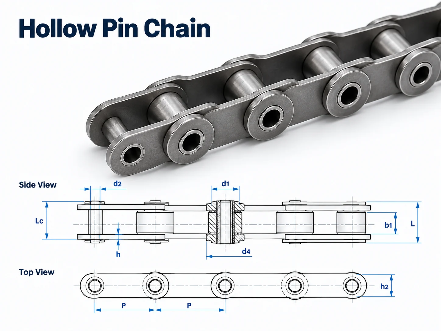
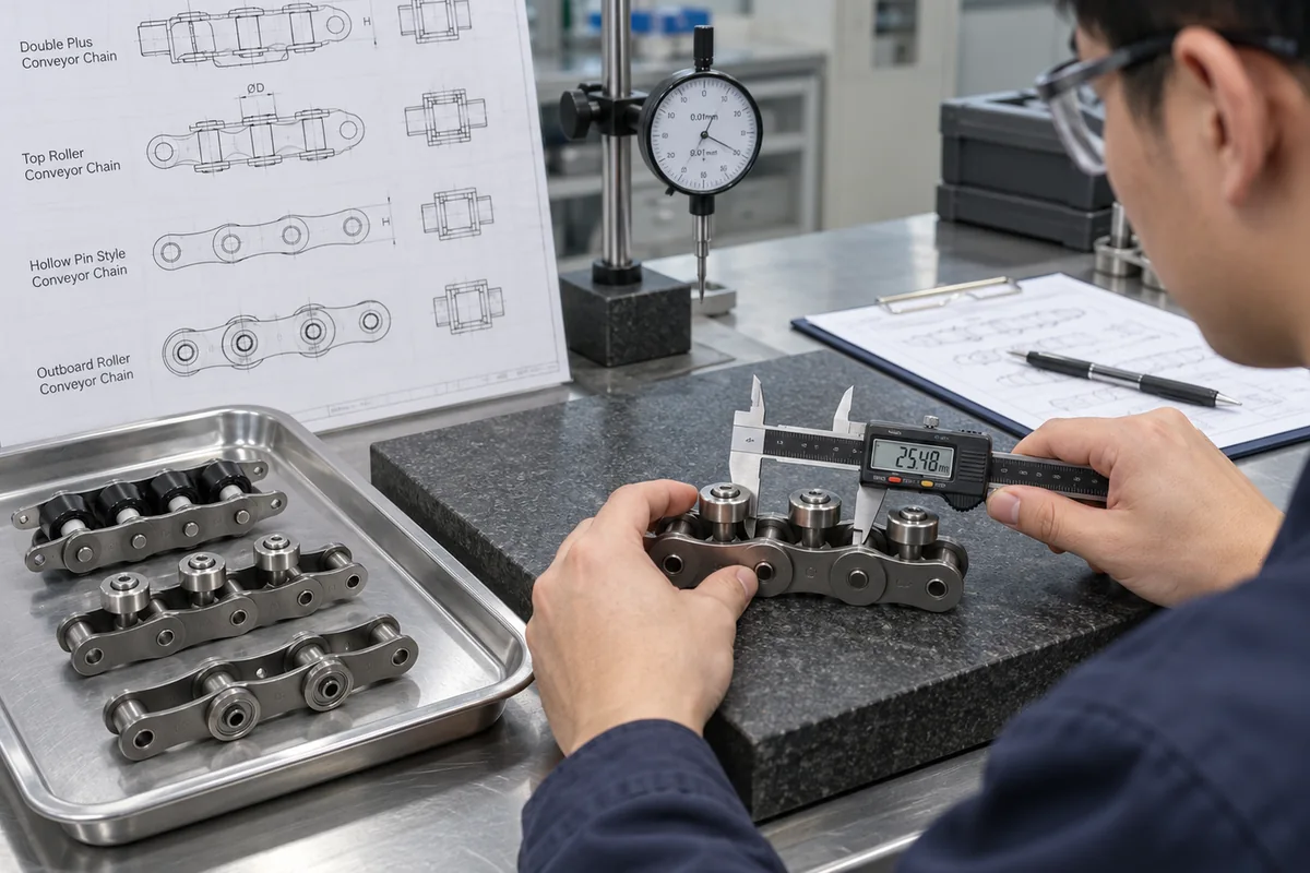
When a model number is available, use the exact model specification and the matching drawing. Compare pitch, roller diameters, inner width, pin diameter and length, plate height and thickness, and any side-roller, large-roller or hollow-pin dimensions that interface with the conveyor. When the code is unknown, measure the installed chain systematically. Measuring pitch across several pins is more reliable than reading a single worn gap, and photographs should show the side profile, roller arrangement, sprocket and rail contact.
Do not use tensile strength as the pallet payload. Catalogue tensile figures are material/component test properties. Conveyor working conditions also involve line length, the number of chain strands, carrier count, acceleration, shock, friction, lubrication, sprocket size, wear state and the required safety factor. The chain can only be verified for a system after those conditions are understood.
Selection workflow
- Carrier Repeatability: compare the required condition with the exact chain drawing or system layout and record any open question for RFQ confirmation.
- Locator Design: compare the required condition with the exact chain drawing or system layout and record any open question for RFQ confirmation.
- Rail Play: compare the required condition with the exact chain drawing or system layout and record any open question for RFQ confirmation.
- Sensor/Stop Sequence: compare the required condition with the exact chain drawing or system layout and record any open question for RFQ confirmation.
- Carrier and duty: record loaded carrier mass, number of carriers, line speed, starts per hour, accumulation pattern and any incline or vertical transition.
- Drive and return: confirm sprocket data, shaft alignment, take-up range, return support and lubrication access.
- Release condition: list any field that the technical data does not state—such as a special material grade, coating, allowable system load or environmental rating—as an RFQ confirmation item instead of estimating it.
System integration
Once the chain is identified, check how the conveyor transfers load into the rest of the machine. The guide or wear rail should support the intended roller surface and remain continuous through joints. Parallel strands should have the specified center distance and synchronized drive timing. Stops should contact a designed pallet face, not the chain side plate. Cross transfers and lifts need enough support so the carrier does not drop into a gap or land on a pin/plate edge.
For systems that accumulate, separate transport from stopping. The chain may continue moving while the carrier is held, but the stop force, queue length, restart sequence and local friction still need to be checked. For systems that position a workpiece for processing, use dedicated locating features when the required repeatability is tighter than normal conveyor transport can provide.
Commissioning and maintenance
Commission a new or repaired conveyor at low speed first. Jog several complete chain circuits and observe the drive, return, rail transitions, stops and transfers. Listen for sounds that repeat once per chain revolution or once per sprocket rotation because those patterns help isolate a tight joint, roller damage, local rail step or sprocket issue. With rigid workpiece pallets, watch for skewing across parallel strands; even small timing differences can load one side of the carrier.
Maintenance should track trends instead of waiting for a failure. Record elongation or length checks using the approved method, inspect rollers for free rotation and abnormal flats, look for polished side-contact marks that suggest misalignment, inspect sprocket teeth and verify take-up position. Lubrication intervals should reflect the operating environment and the chain manufacturer’s guidance; more lubricant is not automatically better if it attracts abrasive contamination or enters a process area.
RFQ checklist
For a replacement request, send the model code if legible, measured pitch, roller arrangement, chain width, plate height, pin dimensions, a photograph of the side profile and a photograph showing sprocket/rail contact. For a new system, add conveyor length, carrier size and loaded mass, number of strands, strand spacing, speed, starts/stops, buffer length, environmental conditions and destination country. These details make it possible to separate a chain match from a full conveyor-duty calculation.
Position from controlled datums, not chain pitch alone
Chain pitch determines transport geometry, but station accuracy also depends on carrier stiffness, guide clearance, locator design, stop repeatability and how process force is supported. Define which surfaces establish the workpiece datum and when the carrier is lifted or clamped away from the conveyor.
Check repeatability with representative loaded fixtures after the line is warm and after several transfers. If position changes with queue length or travel direction, investigate rail, carrier and locator interfaces before attributing the error to the chain.
Measure the interface
Use several-pitch dimensions, end-view geometry and sprocket/rail details when a replacement must fit an existing machine.
Describe the duty
Include loaded carrier mass, speed, starts, accumulation or indexing behavior and the operating environment.
Test the worst case
Commission with representative carriers and the most demanding queue, stop, transfer or restart condition rather than only no-load travel.
Keep open items explicit
If a material, coating, special tolerance, documentation need or allowable system load is not stated, confirm it in the enquiry.
Frequently asked questions
Can I select a replacement from pitch alone?
For positioning accuracy in workpiece carrier systems, pitch is only the first filter. Confirm roller geometry, inner width, pins, plates and any side-roller or hollow-pin features against the installed conveyor before treating two chains as interchangeable.
Does a higher tensile value mean I can carry that load on the pallet?
For positioning accuracy in workpiece carrier systems, do not convert tensile strength directly into pallet payload. Service load depends on strand count, friction, acceleration, stop impact, sprockets, rails and the safety margin used for the machine.
Can a representative family photo prove the exact model?
No. A representative family image can help explain construction, but model identity and dimensions must come from the model-specific technical specification, drawing or confirmed manufacturing data.
What information speeds up a quotation?
For an RFQ related to positioning accuracy in workpiece carrier systems, send the model code or dimensional sketch, clear photographs, conveyor layout, loaded carrier information, quantity and delivery country so the review starts from reproducible machine data.
Key engineering variables for Positioning Accuracy in Workpiece Carrier Systems
The decision should be tied to measurable machine inputs and the exact chain drawing rather than a generic family label. Record the operating case in one line: what the conveyor carries, how fast it moves, where it stops and what condition triggered the review. Capture dimensions and observations another engineer can reproduce.
| Đầu vào | Cần ghi lại những gì | Tại sao điều đó lại quan trọng |
|---|---|---|
| Người vận chuyển/hàng hóa | Loaded mass, center of gravity, underside contact and carrier count | Support, friction and stop behavior |
| Cử động | Speed, starts, stops, accumulation and indexing | Dynamic demand and process timing |
| Chain path | Pitch, rollers, strand spacing and rails | Mechanical fit and tracking |
| Lái xe | Sprocket teeth, alignment, take-up and drive position | Engagement and tension distribution |
| Môi trường | Temperature, dust, moisture, cleaning and lubrication limits | Material and maintenance choices |
Related product and selection resources
Sử dụng pallet conveyor chain catalogue to compare families and the quy trình lựa chọn kỹ thuật when machine data is incomplete.
What to include with an enquiry about Positioning Accuracy in Workpiece Carrier Systems
Identify the installed or proposed chain family, quantity, application, carrier/load, key dimensions and the operating condition the new part must solve. Attach photographs or drawings when the existing code is uncertain and keep open material, documentation or delivery requirements visible.
Connect the chain decision to the production station
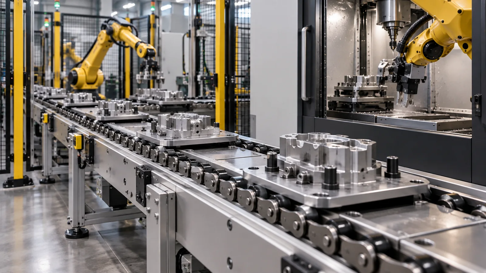
In an automated cell the chain is only one part of the positioning system. Define where the carrier is allowed to float, where it must be guided and where a locator or lift removes process force from the conveyor. Record station spacing, takt time, carrier mass, queue length and the transfer sequence into and out of the station. For robot or inspection cells, check guard openings, sensor locations and the path of cables, clamps or fixtures under the pallet. A chain that runs correctly on a straight test bed can still create problems if the production line introduces side loading, an abrupt rail step or a stop that catches the carrier above the intended contact point. Commission with real pallets and representative stop sequences before increasing speed.
Process
Takt time, station sequence, queue length and whether the carrier passes, stops, locates, lifts or transfers.
Carrier
Loaded mass, footprint, underside geometry, datum features and center of gravity.
Interface
Rail height, strand centers, transfer modules, stops, locators, sensors and guarding clearance.
Trial
No-load tracking first, then representative pallets and worst-case stop/restart sequences.
Separate conveying accuracy from final locating accuracy
The conveyor brings the carrier into a station, but precision work often depends on a separate stop and locating mechanism. Treat those functions independently. First make sure the chain and rails deliver the pallet consistently without side loading; then verify that the stop surface, locator pins or nests repeat against the intended datum faces. Asking the chain alone to provide machine-tool-style positioning can hide the real source of variation.
For a new line, document the required station repeatability, pallet datum scheme, stop direction and any lift-and-locate motion. For an existing line, compare several carriers and stations. If only one station or one pallet drifts, investigate that local interface before changing the chain specification.
Measure the interfaces that control fit and tracking
For Positioning Accuracy in Workpiece Carrier Systems, start with a dimensioned record of the installed conveyor. Measure several pitches rather than one joint, then add roller or pin geometry, plate dimensions, strand centers and the rail/contact section. At the drive, record sprocket tooth count, bore or shaft arrangement and visible tooth wear. At stations, identify stop faces, locators, transfer gaps and the carrier surfaces that actually touch the conveyor.
Repeat the review with a representative loaded pallet at safe low speed. Watch whether the carrier stays square, whether both strands share the load and whether any symptom begins at the same fixed location. A change tied to one rail joint, stop or sprocket should be corrected at that interface before chain tension or a new chain is used as the remedy. Keep photographs of the measurement reference points with the RFQ so an engineer can reproduce the comparison against the proposed drawing.
Chain geometry
Several-pitch length plus roller, pin, plate and attachment dimensions.
Carrier geometry
Loaded mass, underside supports, datums, center of gravity and stop faces.
Drive geometry
Sprocket, shaft, center distance and available take-up travel.
Fixed locations
Rail joints, transfers, stops and points with recurring wear or impact.
Measure repeatability at the process datum, not at the chain
Define the datum surfaces that locate the workpiece and measure repeatability at those surfaces after the carrier has travelled through several transfers. Chain pitch and rail tracking influence transport, but process position also depends on carrier stiffness, guide clearance, stop repeatability and the locator mechanism.
Test the carrier empty and at representative load, then repeat after the line has warmed. If position changes with queue length, travel direction or a particular pallet, investigate the carrier, rail and locator interfaces. A chain replacement should not be expected to correct a loose locating bush or flexible fixture.
For an enquiry, state the required station repeatability and explain how the pallet is stopped, lifted and located. Add carrier mass, strand spacing and the process force applied at the station. That gives the chain supplier enough context to avoid confusing transport geometry with machine-tool accuracy.