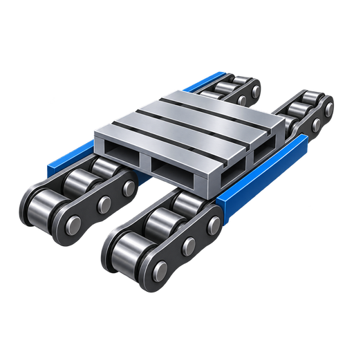
Hollow Pin Conveyor Chain for Custom Fixtures
Practical engineering guide: Hollow Pin Conveyor Chain for Custom Fixtures. Selection, interfaces, application checks, maintenance and RFQ inputs.
This guide focuses on how a hollow pin creates an attachment interface for cross rods and fixtures while the attachment itself needs separate engineering. It is written for machine builders, maintenance teams and buyers who need a chain selection that can be checked against drawings and the real conveyor rather than a generic product label.
Hollow Pin Conveyor Chain for Custom Fixtures
The most useful way to evaluate this subject is to treat the chain as one part of a complete carrier-transport mechanism. In a typical project such as a custom carrier supported from rods passing through hollow pins, chain pitch, roller contact, rail alignment, sprocket engagement, carrier stiffness, stops and maintenance access all influence the result. A useful engineering review therefore combines model-level data with the operating sequence of the machine.

Mengapa isu ini penting
How a hollow pin creates an attachment interface for cross rods and fixtures while the attachment itself needs separate engineering affects more than catalogue selection. It changes how the workpiece carrier enters a station, how loads pass into guide rails, how the chain approaches the drive and how the system behaves during stopping or accumulation. If one interface is ignored, the symptom may appear somewhere else: a roller can wear because a rail joint is high, a chain can pull sideways because a pallet stop is offset, or a new chain can run badly because the old sprocket is worn.
The practical objective is not to eliminate every variation in the machine. It is to identify the variables that must be controlled, define which dimensions are fixed by the chain source, and leave unsupported items for explicit RFQ confirmation. This is also why using chain tensile strength as the allowable cross-rod load is a risky shortcut. It replaces measurable machine data with an assumption and can make a correct-looking part fail at installation.
A hollow pin is an interface, not a finished attachment design. The catalogue bore confirms available opening geometry for the base chain, while cross rods, fixtures and retained parts still require their own bending, shear, retention and clearance checks. Keeping those responsibilities separate prevents the base-chain tensile value from being misused as an attachment rating.
Empat semakan untuk ditakrifkan dahulu
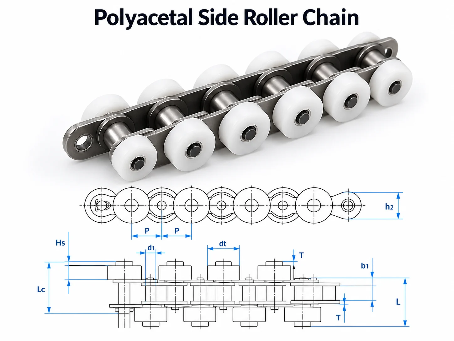
Hollow Bore
Measure this feature from consistent reference surfaces and compare it with the exact model drawing rather than a visual match.
Cross-Rod Diameter
State the measurable condition, installed interface and acceptance check that apply to this part of the conveyor.
Rod Span
State the measurable condition, installed interface and acceptance check that apply to this part of the conveyor.
Attachment Load Direction
State the measurable condition, installed interface and acceptance check that apply to this part of the conveyor.
Mulakan dengan geometri rantai yang tepat
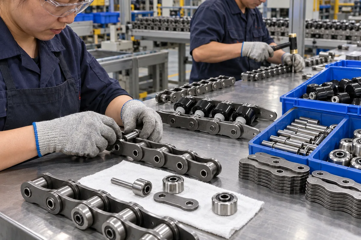
Apabila nombor model tersedia, gunakan spesifikasi model yang tepat dan lukisan yang sepadan. Bandingkan pic, diameter penggelek, lebar dalam, diameter dan panjang pin, ketinggian dan ketebalan plat, dan sebarang dimensi penggelek sisi, penggelek besar atau pin berongga yang bersentuhan dengan penghantar. Apabila kod tidak diketahui, ukur rantai yang dipasang secara sistematik. Mengukur pic merentasi beberapa pin adalah lebih andal daripada membaca satu jurang haus, dan gambar hendaklah menunjukkan profil sisi, susunan penggelek, gegancu dan sentuhan rel.
Do not use tensile strength as the pallet payload. Catalogue tensile figures are material/component test properties. Conveyor working conditions also involve line length, the number of chain strands, carrier count, acceleration, shock, friction, lubrication, sprocket size, wear state and the required safety factor. The chain can only be verified for a system after those conditions are understood.
Aliran kerja pemilihan
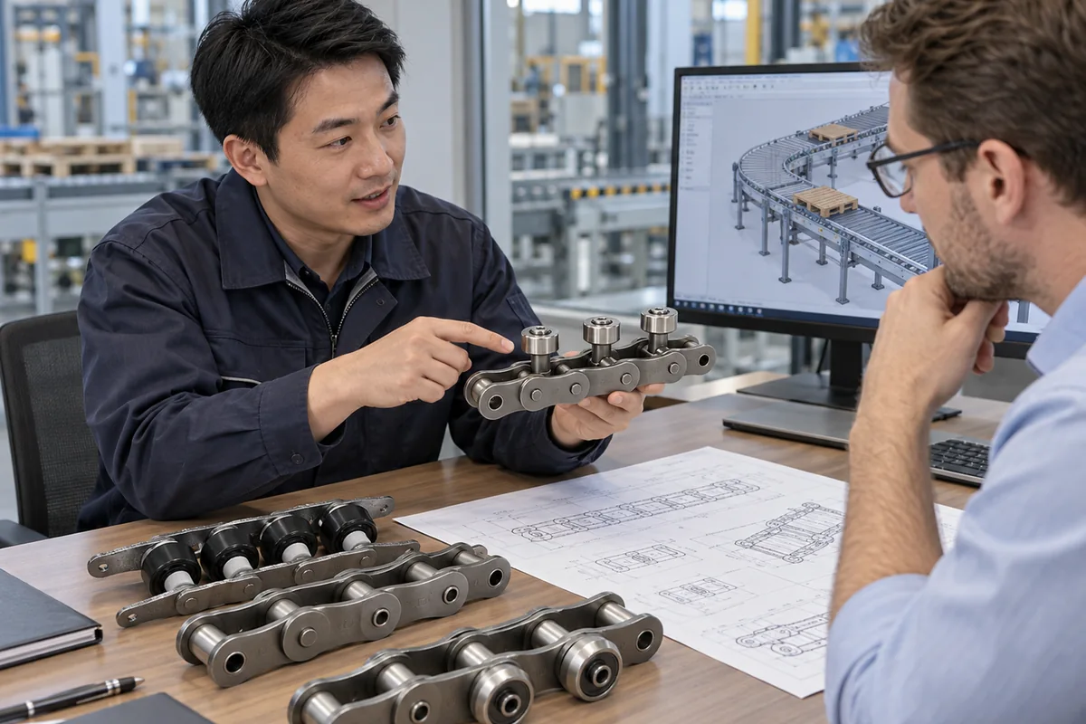
- Hollow Bore: bandingkan keadaan yang diperlukan dengan lukisan rantai atau susun atur sistem yang tepat dan rekodkan sebarang soalan terbuka untuk pengesahan RFQ.
- Cross-Rod Diameter: bandingkan keadaan yang diperlukan dengan lukisan rantai atau susun atur sistem yang tepat dan rekodkan sebarang soalan terbuka untuk pengesahan RFQ.
- Rod Span: bandingkan keadaan yang diperlukan dengan lukisan rantai atau susun atur sistem yang tepat dan rekodkan sebarang soalan terbuka untuk pengesahan RFQ.
- Attachment Load Direction: bandingkan keadaan yang diperlukan dengan lukisan rantai atau susun atur sistem yang tepat dan rekodkan sebarang soalan terbuka untuk pengesahan RFQ.
- Pembawa dan tugas: rekod jisim pembawa yang dimuatkan, bilangan pembawa, kelajuan talian, permulaan sejam, corak pengumpulan dan sebarang peralihan condong atau menegak.
- Memandu dan pulang: sahkan data gegancu, penjajaran aci, jarak pengambilan, sokongan pemulangan dan akses pelinciran.
- Keadaan pelepasan: senaraikan mana-mana medan yang tidak dinyatakan dalam data teknikal—seperti gred bahan khas, salutan, beban sistem yang dibenarkan atau penarafan persekitaran—sebagai item pengesahan RFQ dan bukannya menganggarkannya.
Integrasi sistem
Setelah rantai dikenal pasti, periksa bagaimana penghantar memindahkan beban ke seluruh mesin. Rel panduan atau haus harus menyokong permukaan penggelek yang dimaksudkan dan kekal berterusan melalui sambungan. Untaian selari harus mempunyai jarak tengah yang ditentukan dan pemasaan pemacu yang disegerakkan. Penahan harus bersentuhan dengan permukaan palet yang direka bentuk, bukan plat sisi rantai. Pemindahan silang dan pengangkatan memerlukan sokongan yang mencukupi supaya pembawa tidak jatuh ke dalam jurang atau mendarat di tepi pin/plat.
Bagi sistem yang terkumpul, asingkan pengangkutan daripada pemberhentian. Rantai mungkin terus bergerak semasa pembawa dipegang, tetapi daya pemberhentian, panjang giliran, jujukan mula semula dan geseran setempat masih perlu diperiksa. Bagi sistem yang meletakkan benda kerja untuk pemprosesan, gunakan ciri lokasi khusus apabila kebolehulangan yang diperlukan lebih ketat daripada yang boleh disediakan oleh pengangkutan penghantar biasa.
Pentauliahan dan penyelenggaraan
Mula-mula, gunakan penghantar baharu atau yang telah dibaiki pada kelajuan rendah. Lakukan beberapa litar rantai lengkap dan perhatikan pacuan, pemulangan, peralihan rel, hentian dan pemindahan. Dengar bunyi yang berulang sekali setiap pusingan rantai atau sekali setiap putaran gegancu kerana corak tersebut membantu mengasingkan sambungan yang ketat, kerosakan penggelek, langkah rel setempat atau masalah gegancu. Dengan palet bahan kerja yang tegar, perhatikan kecondongan merentasi untaian selari; perbezaan masa yang kecil pun boleh membebankan satu sisi pembawa.
Penyelenggaraan harus menjejaki trend dan bukannya menunggu kegagalan. Rekodkan pemeriksaan pemanjangan atau panjang menggunakan kaedah yang diluluskan, periksa penggelek untuk putaran bebas dan permukaan rata yang tidak normal, cari tanda sentuhan sisi yang digilap yang menunjukkan salah jajaran, periksa gigi gegancu dan sahkan kedudukan pengambilan. Selang pelinciran harus mencerminkan persekitaran operasi dan panduan pengeluar rantai; lebih banyak pelincir tidak secara automatik lebih baik jika ia menarik pencemaran kasar atau memasuki kawasan proses.
Senarai semak RFQ
Untuk permintaan penggantian, hantarkan kod model jika boleh dibaca, pic yang diukur, susunan penggelek, lebar rantai, ketinggian plat, dimensi pin, gambar profil sisi dan gambar yang menunjukkan sentuhan gegancu/rel. Untuk sistem baharu, tambahkan panjang penghantar, saiz pembawa dan jisim yang dimuatkan, bilangan untaian, jarak untaian, kelajuan, mula/henti, panjang penimbal, keadaan persekitaran dan negara destinasi. Butiran ini membolehkan padanan rantai dipisahkan daripada pengiraan tugas penghantar penuh.
Design the attachment through the hollow pin
The hollow pin provides an interface for cross rods or fixtures, but rod diameter, span, retention and load direction are application details. Define how the attachment transfers force and whether it moves, pivots or remains fixed relative to the chain.
Check clearance through the pin, interference with side plates and sprockets, and support through the return path. When a rod spans between two strands, verify strand centers and carrier stiffness so the rod is not forced to correct conveyor misalignment.
Measure the interface
Use several-pitch dimensions, end-view geometry and sprocket/rail details when a replacement must fit an existing machine.
Describe the duty
Include loaded carrier mass, speed, starts, accumulation or indexing behavior and the operating environment.
Test the worst case
Commission with representative carriers and the most demanding queue, stop, transfer or restart condition rather than only no-load travel.
Keep open items explicit
If a material, coating, special tolerance, documentation need or allowable system load is not stated, confirm it in the enquiry.
Soalan lazim
Bolehkah saya memilih pengganti daripada pitch sahaja?
For hollow pin conveyor chain for custom fixtures, pitch is only the first filter. Confirm roller geometry, inner width, pins, plates and any side-roller or hollow-pin features against the installed conveyor before treating two chains as interchangeable.
Adakah nilai tegangan yang lebih tinggi bermakna saya boleh membawa beban tersebut di atas palet?
For hollow pin conveyor chain for custom fixtures, do not convert tensile strength directly into pallet payload. Service load depends on strand count, friction, acceleration, stop impact, sprockets, rails and the safety margin used for the machine.
Bolehkah gambar keluarga yang mewakili membuktikan model yang tepat?
Tidak. Imej keluarga yang representatif boleh membantu menjelaskan pembinaan, tetapi identiti dan dimensi model mesti datang daripada spesifikasi teknikal khusus model, lukisan atau data pembuatan yang disahkan.
Maklumat apakah yang mempercepatkan sebut harga?
For an RFQ related to hollow pin conveyor chain for custom fixtures, send the model code or dimensional sketch, clear photographs, conveyor layout, loaded carrier information, quantity and delivery country so the review starts from reproducible machine data.
Key engineering variables for Hollow Pin Conveyor Chain for Custom Fixtures
Hollow-pin selection must define the cross rod, fixture or attachment interface passing through the pin. Record the operating case in one line: what the conveyor carries, how fast it moves, where it stops and what condition triggered the review. Capture dimensions and observations another engineer can reproduce.
| Input | Apa yang perlu direkodkan | Mengapa ia penting |
|---|---|---|
| Pembawa/beban | Jisim beban, pusat graviti, sentuhan bawah dan kiraan pembawa | Sokongan, geseran dan tingkah laku henti |
| Gerakan | Kelajuan, permulaan, penghentian, pengumpulan dan pengindeksan | Permintaan dinamik dan masa proses |
| Laluan rantai | Pitch, penggelek, jarak untaian dan rel | Padanan dan penjejakan mekanikal |
| Pandu | Gigi gegancu, penjajaran, kedudukan pengambilan dan pemacu | Penglibatan dan pengagihan ketegangan |
| Alam Sekitar | Had suhu, habuk, kelembapan, pembersihan dan pelinciran | Pilihan bahan dan penyelenggaraan |
Related product and selection resources
Gunakan katalog rantai penghantar palet untuk membandingkan keluarga dan aliran kerja pemilihan kejuruteraan when machine data is incomplete. For adjacent component context, see industrial mechanical chain families.
What to include with an enquiry about Hollow Pin Conveyor Chain for Custom Fixtures
Kenal pasti keluarga rantai yang dipasang atau dicadangkan, kuantiti, aplikasi, pembawa/beban, dimensi utama dan keadaan operasi yang mesti diselesaikan oleh bahagian baharu. Lampirkan gambar atau lukisan apabila kod sedia ada tidak pasti dan pastikan bahan, dokumentasi atau keperluan penghantaran yang terbuka kelihatan.
Make the selection from interfaces, not from one catalogue dimension
A useful selection sequence starts with the carrier and rail, then moves to the chain and sprocket. Measure several pitches, identify the roller arrangement and compare plate height, pin dimensions and roller position against the drawing. Confirm the sprocket tooth count and bore and check whether the chain enters the rail smoothly after leaving the sprocket. For side-roller or hollow-pin designs, include the outboard rail or cross-rod interface in the same review. For Double Plus layouts, state the required conveying and accumulation behavior together with queue length and stop sequence. If any key dimension is unknown, leave it as an RFQ confirmation item instead of filling it from a neighboring model.
Geometry
Pitch over several joints, roller arrangement, pin/plate dimensions and strand spacing.
Pandu
Sprocket tooth count, bore, shaft alignment, take-up and chain entry/exit geometry.
Duty
Speed, starts per hour, maximum queue, carrier mass and environmental conditions.
Confirm the model
Compare the complete model drawing and list any unstated material, tolerance or application requirement in the enquiry.
Capture the special interface as well as the base chain
For Hollow Pin Conveyor Chain for Custom Fixtures, the feature that differentiates the family must be measured directly. Side-roller chains need an end view showing roller diameter, offset and rail contact. Hollow-pin chains need pin-bore and cross-rod information, including rod span and retention. Material-specific versions also need the real operating environment stated separately from their dimensions. A nominal pitch or side photograph alone is not enough to confirm interchangeability.
Follow the special feature through the complete loop. Check rail joints, transfers, sprocket approach, return support and any location where a rod, roller or fastener could lose clearance. If two strands are connected by a carrier or cross rod, compare strand centers and take-up positions. For an RFQ, combine the exact geometry with loaded carrier information, speed, stop/queue behavior and any special material or documentation requirement; this keeps mechanical fit and application suitability visible as separate checks.
End view
Show roller offset, hollow-pin bore or attachment relationship to the chain body.
Clearance
Check rails, sprockets, return supports, guards and transfer gaps.
Load path
Identify how the carrier, fixture or cross rod transfers force.
Service condition
State environment, cleaning, lubrication and material/document requirements.
Check the attachment load path through the hollow pin
Measure the hollow-pin bore and define the cross rod or attachment that passes through it: diameter, unsupported span, retention method and material requirement. Draw how the fixture load reaches the rod and whether the rod rotates, slides or remains fixed. The chain model does not automatically define those attachment details.
Rotate the conveyor by hand or at safe low speed and check clearance around side plates, sprockets, rails and guards. Pay particular attention to the return path, where a rod or fastener that clears the loaded section can still collide with support structure. If one rod spans two chain strands, verify strand centers and alignment.
For a replacement, photograph the existing rod from the side and end and include the reason for replacement. For a new fixture, state carrier/load, stop sequence and any process force. Where possible, use station supports to carry process loads instead of transmitting them through the chain attachment.