Engineering Cross Rods for Hollow Pin Chain
Practical engineering guide: Engineering Cross Rods for Hollow Pin Chain. Selection, interfaces, application checks, maintenance and RFQ inputs.
This guide focuses on how rod material, span, connection and bending load must be checked separately from the base chain. It is written for machine builders, maintenance teams and buyers who need a chain selection that can be checked against drawings and the real conveyor rather than a generic product label.
Engineering Cross Rods for Hollow Pin Chain
Many conveyor problems begin when a correct catalogue component is installed into an interface that was never checked in detail. In a typical project such as a fixture conveyor with rods connecting two parallel chain strands, chain pitch, roller contact, rail alignment, sprocket engagement, carrier stiffness, stops and maintenance access all influence the result. A useful engineering review therefore combines model-level data with the operating sequence of the machine.
Warum dieses Thema wichtig ist
How rod material, span, connection and bending load must be checked separately from the base chain affects more than catalogue selection. It changes how the workpiece carrier enters a station, how loads pass into guide rails, how the chain approaches the drive and how the system behaves during stopping or accumulation. If one interface is ignored, the symptom may appear somewhere else: a roller can wear because a rail joint is high, a chain can pull sideways because a pallet stop is offset, or a new chain can run badly because the old sprocket is worn.
The practical objective is not to eliminate every variation in the machine. It is to identify the variables that must be controlled, define which dimensions are fixed by the chain source, and leave unsupported items for explicit RFQ confirmation. This is also why choosing the rod solely because it fits through the bore is a risky shortcut. It replaces measurable machine data with an assumption and can make a correct-looking part fail at installation.
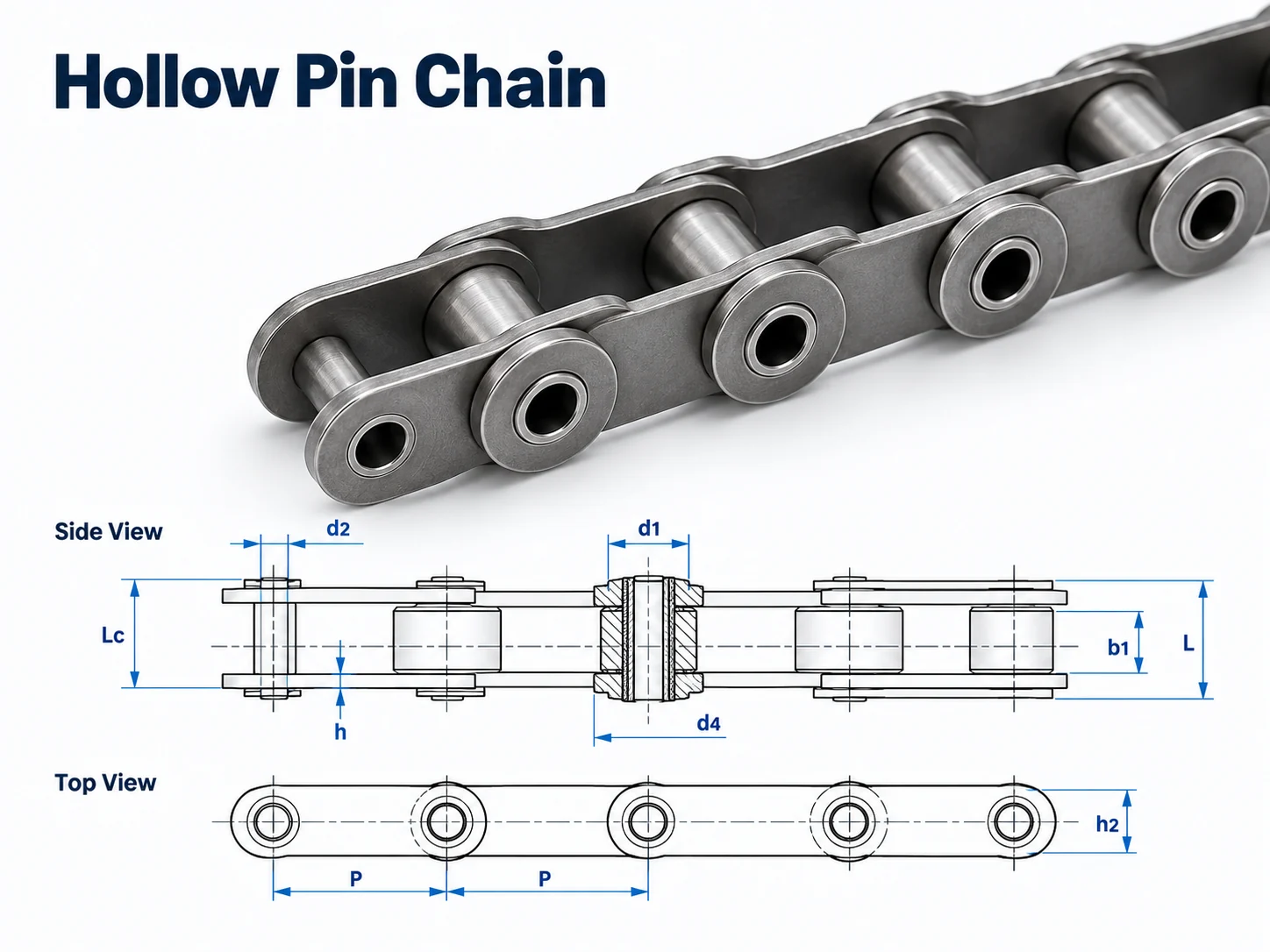
A hollow pin is an interface, not a finished attachment design. The catalogue bore confirms available opening geometry for the base chain, while cross rods, fixtures and retained parts still require their own bending, shear, retention and clearance checks. Keeping those responsibilities separate prevents the base-chain tensile value from being misused as an attachment rating.
Vier Prüfungen zur Definition von ersten
Bore Clearance
Measure this feature from consistent reference surfaces and compare it with the exact model drawing rather than a visual match.
Rod Material
State the measurable condition, installed interface and acceptance check that apply to this part of the conveyor.
Unsupported Span
State the measurable condition, installed interface and acceptance check that apply to this part of the conveyor.
Retention Method
State the measurable condition, installed interface and acceptance check that apply to this part of the conveyor.
Beginnen Sie mit der exakten Kettengeometrie.
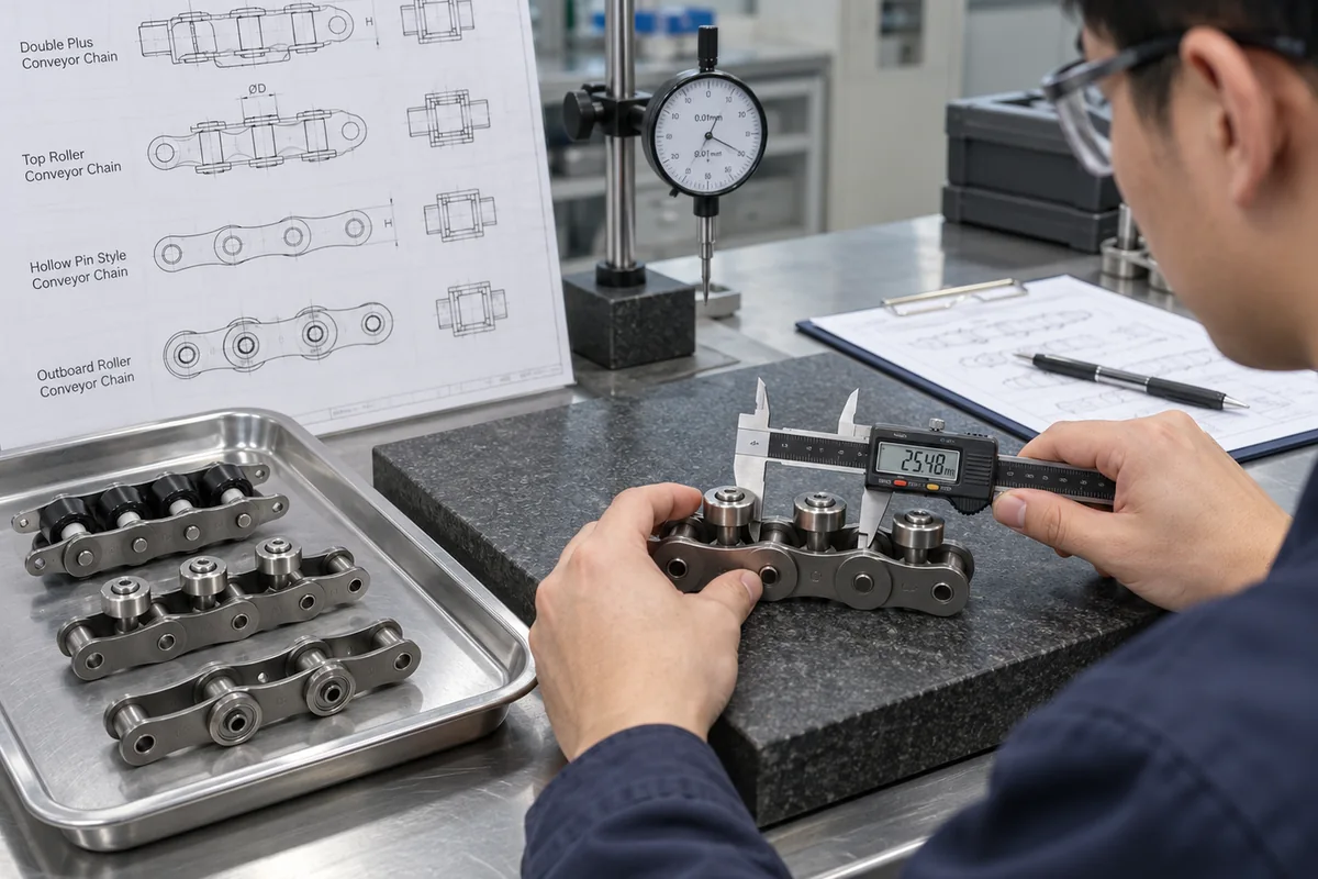
Wenn eine Modellnummer verfügbar ist, verwenden Sie die exakte Modellspezifikation und die zugehörige Zeichnung. Vergleichen Sie Teilung, Rollendurchmesser, Innenbreite, Bolzendurchmesser und -länge, Plattenhöhe und -dicke sowie alle Abmessungen von Seitenrollen, Großrollen oder Hohlbolzen, die mit dem Förderer in Kontakt stehen. Ist der Code unbekannt, messen Sie die installierte Kette systematisch. Die Messung der Teilung über mehrere Bolzen ist zuverlässiger als die Messung eines einzelnen verschlissenen Spalts. Fotos sollten das Seitenprofil, die Rollenanordnung sowie den Kontakt von Kettenrad und Schiene zeigen.
Do not use tensile strength as the pallet payload. Catalogue tensile figures are material/component test properties. Conveyor working conditions also involve line length, the number of chain strands, carrier count, acceleration, shock, friction, lubrication, sprocket size, wear state and the required safety factor. The chain can only be verified for a system after those conditions are understood.
Auswahl-Workflow
- Bore Clearance: Vergleichen Sie die geforderten Bedingungen mit der genauen Kettenzeichnung oder dem Systemlayout und notieren Sie alle offenen Fragen zur Bestätigung der Angebotsanfrage.
- Rod Material: Vergleichen Sie die geforderten Bedingungen mit der genauen Kettenzeichnung oder dem Systemlayout und notieren Sie alle offenen Fragen zur Bestätigung der Angebotsanfrage.
- Unsupported Span: Vergleichen Sie die geforderten Bedingungen mit der genauen Kettenzeichnung oder dem Systemlayout und notieren Sie alle offenen Fragen zur Bestätigung der Angebotsanfrage.
- Retention Method: Vergleichen Sie die geforderten Bedingungen mit der genauen Kettenzeichnung oder dem Systemlayout und notieren Sie alle offenen Fragen zur Bestätigung der Angebotsanfrage.
- Spediteur und Dienst: Erfasst werden die Masse des beladenen Förderers, die Anzahl der Förderer, die Liniengeschwindigkeit, die Starts pro Stunde, das Staumuster sowie etwaige Steigungen oder vertikale Übergänge.
- Hin- und Rückfahrt: Überprüfen Sie die Daten des Kettenrads, die Wellenausrichtung, den Spannbereich, die Rücklaufunterstützung und den Schmierzugang.
- Freigabebedingungen: Alle Felder, die in den technischen Daten nicht angegeben sind – wie z. B. eine spezielle Materialgüte, Beschichtung, zulässige Systemlast oder Umweltklasse – sollten als RFQ-Bestätigungspunkt aufgeführt werden, anstatt sie zu schätzen.
Systemintegration
Sobald die Förderkette identifiziert ist, prüfen Sie, wie die Last vom Förderband in die restliche Maschine übertragen wird. Die Führungsschiene bzw. Verschleißschiene muss die vorgesehene Rollenoberfläche stützen und an den Verbindungsstellen durchgehend sein. Parallele Kettenstränge müssen den vorgegebenen Achsabstand und die synchronisierte Antriebstaktung aufweisen. Anschläge müssen an der vorgesehenen Palettenfläche und nicht an der Kettenseitenplatte anliegen. Querübergaben und Hubvorgänge benötigen ausreichende Unterstützung, damit der Träger nicht in eine Lücke gerät oder auf einer Bolzen-/Plattenkante aufsetzt.
Bei Systemen mit Materialstau müssen Transport und Stopp getrennt werden. Die Kette kann sich weiterbewegen, während der Träger angehalten wird; Stoppkraft, Warteschlangenlänge, Wiederanlaufsequenz und lokale Reibung müssen jedoch weiterhin überprüft werden. Bei Systemen, die ein Werkstück für die Bearbeitung positionieren, sollten spezielle Positionierelemente verwendet werden, wenn die erforderliche Wiederholgenauigkeit über den Rahmen des normalen Förderbandtransports hinausgeht.
Inbetriebnahme und Instandhaltung
Nehmen Sie ein neues oder repariertes Förderband zunächst mit niedriger Geschwindigkeit in Betrieb. Führen Sie mehrere vollständige Kettenumläufe durch und beobachten Sie dabei Antrieb, Rücklauf, Schienenübergänge, Stopps und Materialübergaben. Achten Sie auf Geräusche, die sich einmal pro Kettenumdrehung oder Kettenradumdrehung wiederholen, da diese Muster Hinweise auf schwergängige Verbindungen, beschädigte Rollen, lokale Schienenstufen oder Probleme mit den Kettenrädern geben. Bei starren Werkstückpaletten ist auf Schräglagen zwischen parallelen Strängen zu achten; selbst geringe Timing-Unterschiede können zu einseitiger Belastung des Förderers führen.
Die Instandhaltung sollte Trends verfolgen, anstatt auf einen Ausfall zu warten. Längen- und Dehnungsmessungen sind gemäß der zugelassenen Methode zu dokumentieren. Die Rollen sind auf freie Drehung und ungewöhnliche Abflachungen zu prüfen. Polierte Seitenkontaktspuren, die auf eine Fehlausrichtung hindeuten, sind zu erkennen. Die Kettenradzähne sind zu prüfen und die Spannposition zu verifizieren. Die Schmierintervalle sollten sich nach den Betriebsbedingungen und den Empfehlungen des Kettenherstellers richten; mehr Schmierstoff ist nicht automatisch besser, wenn er abrasive Verunreinigungen anzieht oder in einen Prozessbereich gelangt.
Checkliste für Angebotsanfragen
Für eine Ersatzteilanfrage senden Sie bitte, falls lesbar, die Modellbezeichnung, die gemessene Teilung, die Rollenanordnung, die Kettenbreite, die Plattenhöhe, die Bolzenabmessungen, ein Foto des Seitenprofils und ein Foto, das den Kontakt zwischen Kettenrad und Schiene zeigt. Für eine neue Anlage benötigen wir zusätzlich die Förderbandlänge, die Trägergröße und die Ladungsmasse, die Anzahl der Litzen, den Litzenabstand, die Geschwindigkeit, die Start-/Stopp-Zeiten, die Pufferlänge, die Umgebungsbedingungen und das Zielland. Diese Angaben ermöglichen es, die Kettenanpassung von der Berechnung der Gesamtförderleistung zu trennen.
Size the cross-rod as a separate machine element
A cross rod should be reviewed for diameter, unsupported span, material, retention method and the way its load reaches the fixture or carrier. Those items are not automatically defined by the hollow-pin chain model.
Also check assembly and maintenance access: the rod must be insertable and removable without damaging the chain, and retaining hardware must clear rails, sprockets and guards throughout the loop. Photograph an existing rod installation when requesting a replacement.
Measure the interface
Use several-pitch dimensions, end-view geometry and sprocket/rail details when a replacement must fit an existing machine.
Describe the duty
Include loaded carrier mass, speed, starts, accumulation or indexing behavior and the operating environment.
Test the worst case
Commission with representative carriers and the most demanding queue, stop, transfer or restart condition rather than only no-load travel.
Keep open items explicit
If a material, coating, special tolerance, documentation need or allowable system load is not stated, confirm it in the enquiry.
Häufig gestellte Fragen
Kann ich einen Ersatz nur anhand der Tonhöhe auswählen?
For engineering cross rods for hollow pin chain, pitch is only the first filter. Confirm roller geometry, inner width, pins, plates and any side-roller or hollow-pin features against the installed conveyor before treating two chains as interchangeable.
Bedeutet ein höherer Zugfestigkeitswert, dass ich diese Last auf der Palette tragen kann?
For engineering cross rods for hollow pin chain, do not convert tensile strength directly into pallet payload. Service load depends on strand count, friction, acceleration, stop impact, sprockets, rails and the safety margin used for the machine.
Kann ein repräsentatives Familienfoto das genaue Modell beweisen?
Nein. Ein repräsentatives Familienbild kann zwar zur Erläuterung der Konstruktion beitragen, die Modellidentität und die Abmessungen müssen jedoch aus der modellspezifischen technischen Spezifikation, der Zeichnung oder den bestätigten Fertigungsdaten stammen.
Welche Informationen beschleunigen die Angebotserstellung?
For an RFQ related to engineering cross rods for hollow pin chain, send the model code or dimensional sketch, clear photographs, conveyor layout, loaded carrier information, quantity and delivery country so the review starts from reproducible machine data.
Key engineering variables for Engineering Cross Rods for Hollow Pin Chain
Hollow-pin selection must define the cross rod, fixture or attachment interface passing through the pin. Record the operating case in one line: what the conveyor carries, how fast it moves, where it stops and what condition triggered the review. Capture dimensions and observations another engineer can reproduce.
| Eingang | Was aufgezeichnet werden soll | Warum es wichtig ist |
|---|---|---|
| Träger/Ladung | Beladene Masse, Schwerpunkt, Unterseitenkontakt und Trägeranzahl | Unterstützung, Reibung und Stoppverhalten |
| Bewegung | Geschwindigkeit, Starts, Stopps, Akkumulation und Indexierung | Dynamische Nachfrage und Prozesszeitplanung |
| Kettenpfad | Teilung, Rollen, Litzenabstand und Schienen | Mechanische Passform und Nachführung |
| Fahren | Kettenradzähne, Ausrichtung, Spann- und Antriebsposition | Engagement und Spannungsverteilung |
| Umfeld | Grenzwerte für Temperatur, Staub, Feuchtigkeit, Reinigung und Schmierung | Material- und Wartungsoptionen |
Related product and selection resources
Verwenden Sie die Katalog für Palettenförderketten um Familien und die Auswahlprozess für Ingenieure wenn Maschinendaten unvollständig sind.
What to include with an enquiry about Engineering Cross Rods for Hollow Pin Chain
Geben Sie die installierte oder geplante Kettenfamilie, die Anzahl, die Anwendung, das Träger-/Lastsystem, die wichtigsten Abmessungen und die Betriebsbedingungen an, die das neue Bauteil erfüllen muss. Fügen Sie Fotos oder Zeichnungen bei, wenn die geltenden Normen unklar sind, und halten Sie offene Material-, Dokumentations- oder Lieferanforderungen offen.
Make the selection from interfaces, not from one catalogue dimension
A useful selection sequence starts with the carrier and rail, then moves to the chain and sprocket. Measure several pitches, identify the roller arrangement and compare plate height, pin dimensions and roller position against the drawing. Confirm the sprocket tooth count and bore and check whether the chain enters the rail smoothly after leaving the sprocket. For side-roller or hollow-pin designs, include the outboard rail or cross-rod interface in the same review. For Double Plus layouts, state the required conveying and accumulation behavior together with queue length and stop sequence. If any key dimension is unknown, leave it as an RFQ confirmation item instead of filling it from a neighboring model.
Geometry
Pitch over several joints, roller arrangement, pin/plate dimensions and strand spacing.
Fahren
Sprocket tooth count, bore, shaft alignment, take-up and chain entry/exit geometry.
Duty
Speed, starts per hour, maximum queue, carrier mass and environmental conditions.
Confirm the model
Compare the complete model drawing and list any unstated material, tolerance or application requirement in the enquiry.
Capture the special interface as well as the base chain
For Engineering Cross Rods for Hollow Pin Chain, the feature that differentiates the family must be measured directly. Side-roller chains need an end view showing roller diameter, offset and rail contact. Hollow-pin chains need pin-bore and cross-rod information, including rod span and retention. Material-specific versions also need the real operating environment stated separately from their dimensions. A nominal pitch or side photograph alone is not enough to confirm interchangeability.
Follow the special feature through the complete loop. Check rail joints, transfers, sprocket approach, return support and any location where a rod, roller or fastener could lose clearance. If two strands are connected by a carrier or cross rod, compare strand centers and take-up positions. For an RFQ, combine the exact geometry with loaded carrier information, speed, stop/queue behavior and any special material or documentation requirement; this keeps mechanical fit and application suitability visible as separate checks.
End view
Show roller offset, hollow-pin bore or attachment relationship to the chain body.
Clearance
Check rails, sprockets, return supports, guards and transfer gaps.
Load path
Identify how the carrier, fixture or cross rod transfers force.
Service condition
State environment, cleaning, lubrication and material/document requirements.
Treat the cross rod as a separate structural component
Record rod diameter, free span, material, end retention and any threaded or machined features. Determine whether it carries steady weight, indexing force, impact or only locates a lightweight fixture. These are cross-rod design inputs and should not be inferred from the hollow-pin chain model.
Check assembly access as well as operating clearance. The rod must be installable and removable without forcing the chain plates, and retaining hardware must clear sprockets, rails and guards throughout the loop. If the rod connects two strands, compare strand centers and take-up positions so the rod is not used to pull misaligned chains together.
During commissioning, inspect for bending, fretting or contact marks after representative load cycles. Include a sketch of the complete rod and fixture with the chain enquiry. This separates the chain interface from the custom attachment engineering that sits between the strands.